Tag: embedded

lzoDSO – DIY oscilloscopes a waste of time?

Posted by April 15, 2013

After watching the rant from Dave Jones (from the EEVblog) in his car expressing his opinion on DIY micro controller-based oscilloscopes one might think there is no merit to building such a device. Well, in my opinion there is! Okay, Dave also made this point clear: it is okay to build one for getting your feet wet in the electronics and embedded systems domain. Which is exactly what I am doing.

To further address the criticism of Dave by saying that those DIY scopes usually do not have any thought put into the analog front-end (AFE) or the trigger section. In general I’d approve his observations.

So why is the lzoDSO not going to be a simple DIY scope? Because we actually want to delve down into the dirty details of constructing an AFE and a trigger section that act just like the ones an electrical engineer would expect from a typical digital storage oscilloscope.

Even though these are two of the paramount parts of an oscilloscope, first we will bring our prototype to a state where it can be helpful in evaluation the design of an AFE and a trigger section.

UPDATE: As Dave suggested I started asking around for someone who might pass me his old oscilloscope. If you have one you want to pass on to someone who will gain from even an old analog or digital device: please contact me (see contact) and maybe I can compensate you in one way or the other. Anyways, don’t think this will stop me from continuing to work on the lzoDSO.

lzoDSO – legacy firmware reanimated

Posted by April 12, 2013

After preparing a somewhat more modest presentation of what is already existing from the projects hardware and software (we now call it the prototype), we have finally taken the old “legacy” (no tests) firmware sources and made them work (without having to change anything) on the ATmega644 micro controller board we use with the prototype setup.

Still, there is so much missing but before adding more functionality to the firmware we will try to replace part by part with code that is developed in a “test first” fashion to give us a stable base to work on. But before that can happen will need to refactor some sections of the sources in order to make them testable.

Enough for today…maybe

lzoDSO – hardware prototype

Posted by April 11, 2013

IMG_0257_modified-small
lzoDSO hardware prototype

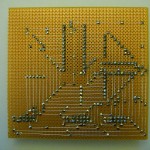
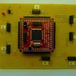
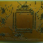
Recently I have been working on my oscilloscope project. Documenting ideas, digging out requirements and restructuring the whole projects documentation wiki. While doing so I realized that the page was totally confusing to new visitors since it does not say that there is no finished scope yet (even though there is a picture of one). What one can see on the pictures is actually a prototype. Until now we did not explicitly say so. This is NOT the final thing.

To address that issue we added a Status section to the start page of the wiki that clarifies the projects state.

Now the interesting part: We created a new page for the prototype which is linked on the wikis start page and moved existing files related to the components of the prototype from /trunk to /branches/prototype-a.

Next step will be to take the legacy firmware we have and adjusted it to make it run on the prototype hardware. When the firmware is ported (basically adjust pin mappings, enable/disable functionality) we will use is as the starting point to get the code incrementally refactored until we replaced everything with test-driven code.

lzoDSO – a DIY Oscilloscope

Posted by March 19, 2013

After quiet a while I have started to put my oscilloscope project online. Work is still in progress but I decided it won’t hurt to have online what has been done so far.

The End of Embedded Linux


The Embedded Linux Quick Start Guide


test-driven development for embedded systems


Found a nice article at embedded.com on how mocking can help build more robust and clear code. The article talks about development using C/C++ and the Unity unit testing framework which I have been using for quiet a while (thanks to the book “Test-Driven Development for Embedded C” by James Grenning).


external memory board


Just before writing my last post, I started building another board in order to supply my ATmega128 with 64Kbytes of external memory (in fact the so called “XMEM” feature was one of the reasons I bought that chip).

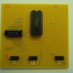
The board is designed for a 28 pin S-RAM IC (Hitachi HM6264) that can be connected to a micro controller supporting external memory (like the ATmega128 or ATmega162) using three 10 pin headers. The first header is used for the multiplexed lower address/IO bits (port A on micro controller), the second for dedicated upper address bits (port C) and the last for read/write strobe and address latch enable (port G). All headers share two common last pins: GND (9) and VCC (10). The only thing required except for the S-RAM itself, some pin headers and a 100uF ceramic capacitor is a octal latch IC (74AHC573) that will allow for multiplexing the shared lower address/IO lines.

NOTE

After looking up the “Address Latch Requirements” section in the ATmega128 datasheet turns out that when the micro controller is operated above 8MHz (mine has a 16MHz crystal) the 74HC573 (the IC I have) does not meet requirements but a 74AHC573 would do. I guess I will put in a 8MHz crystal until I can get hold of a 74AHC573.


Download

base board for Olimex ATmega128 header board


A couple of months ago I ordered a ATmega128 header board (AVR-H128) from Olimex. In order to make use of such a header board you need to mount it somewhere. For this purpose I created a sort of header board for the header board. It is very minimal, consisting of mechanical components only except for a LED and a resistor. The reason for that is that the header board on which the ATmega128 itself is placed already contains a +5V voltage regulator (LM78L05) and reset circuit (ZM33064). Using my board its very convenient connecting things to the pins of the micro controller. All ports (A, B, C, D, E, F and G) have a separate 10 (2×5) pin header where the last two pins of each header is connected to GND (9) and VCC (10).

The layout of the board was created with the intention in mind to be able to assemble it in a through-hole fashion. Needless to say that the layout can also be used to etch or mill the board.

There are still things that can be enhanced like adding a connector for the reference voltage of the ADC (AREF).

Download

Schematics and layout have been created using Eagle 5.11 with a non-commercial license. The outline of the board is 100x160mm, so for you folks that use the Eagle freeware you will not be able to modify the boards layout (since Eagle as freeware only allows for boards with a outline of 100x80mm).

Reading “Test-Driven Development for Embedded C”

Posted by May 8, 2011

jgadeThursday this week I received my copy of “Test-Driven Development for Embedded C” by James W. Grenning. This was just the book I have been looking for months. I had the problem of developing a micro controller firmware in C but without tests. The reasons I had not started the project in a “test first” fashion were too many. Questions like “how do I test code that needs the hardware to run” as well as the limitations of only using free and open source software were and still are barriers I hope this book will help me overcome.